Existing Steely units
With complete selections, receive a project-specific concept rendering and preliminary cost estimate targeted for the same business day.
What you receive
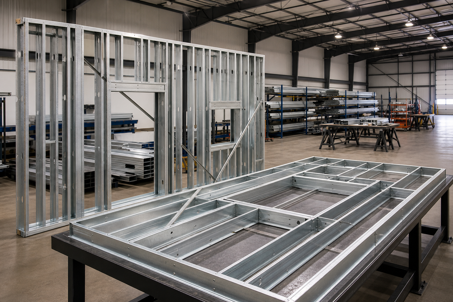
Steely connects the rendering, measured drawings, preliminary estimate, steel-system data, engineer handoff, and physical package so the same project intent carries from the first conversation into production.
Fast first answers
Timing begins when the dimensions, use, roof, openings, site, and requested scope are complete enough to review.
With complete selections, receive a project-specific concept rendering and preliminary cost estimate targeted for the same business day.
Provide a plan, sketch, or measured idea for an initial coordinated design review, rendering direction, and estimate basis.
Once geometry and site criteria are confirmed, the steel scope is organized into the information needed for licensed engineering review.
These are workflow targets—not promises of an engineer's stamp, permit approval, fabrication release, or authority review. Complex structures, incomplete inputs, revisions, and local requirements can change timing.
Your digital project packet
A realistic exterior concept tied to the selected roof family, footprint, wall heights, openings, colors, and setting.
A measured early estimate based on the selected model, geometry, openings, steel basis, delivery scope, and known project information.
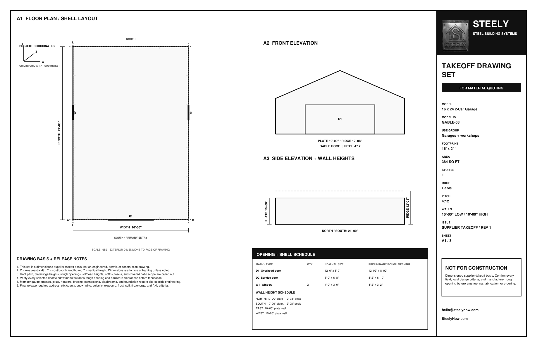
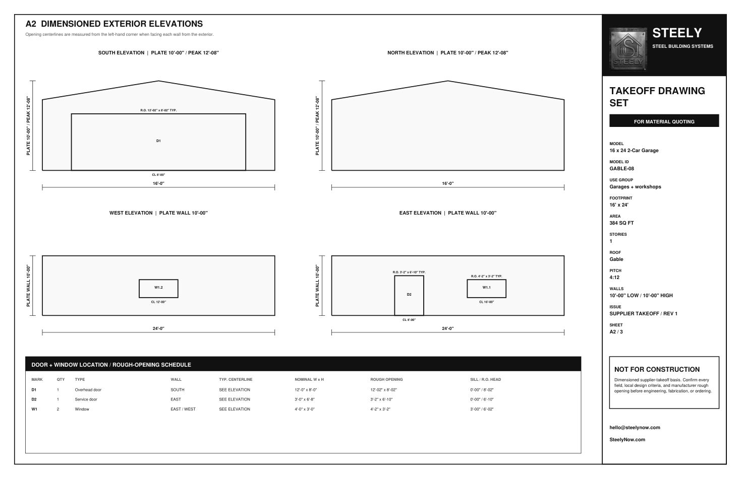
Black-and-white floor plan, four elevations, wall and plate heights, roof pitch, X/Y/Z references, and covered-area dimensions.
Door and window sizes, rough-opening widths and heights, sill and head heights, wall locations, and special large-opening notes.
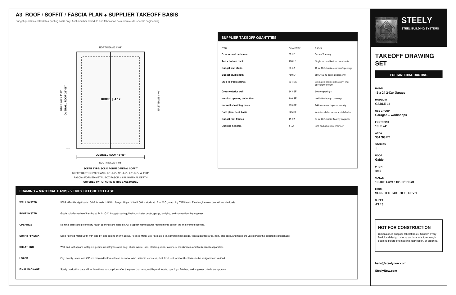
Roof geometry, pitch, ridge or high/low walls, all four overhangs, soffit system, fascia type, and fascia depth.
Budget framing basis, wall area, roof area, track, stud length, fasteners, cladding interface, and other supplier-quoting quantities.
Wall, floor, roof, opening, member, panel, header, truss, joist, bracing, and connection information developed for the selected scope.
A shareable digital view of the model, selected dimensions, documents, assumptions, and outstanding decisions before release.
Example: 16 × 24 two-car garage
The example combines the finished-building direction with a three-sheet supplier-takeoff set. Page A1 establishes the shell and floor plan. A2 dimensions all four walls and rough openings. A3 carries roof pitch, soffits, fascia, overhangs, and the preliminary framing and material basis.
Different roof + truss families
A gable garage, compact gambrel shed, and custom shop each need their own roof geometry, openings, wall heights, engineering assumptions, and matching drawing set.
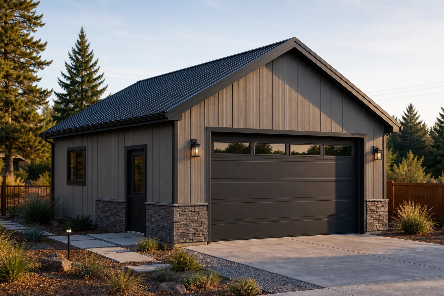
Classic gable
A conventional two-slope roof and gable-truss starting point with garage-door, service-door, window, wall-height, ridge, soffit, fascia, and roof callouts.
Open matching drawing set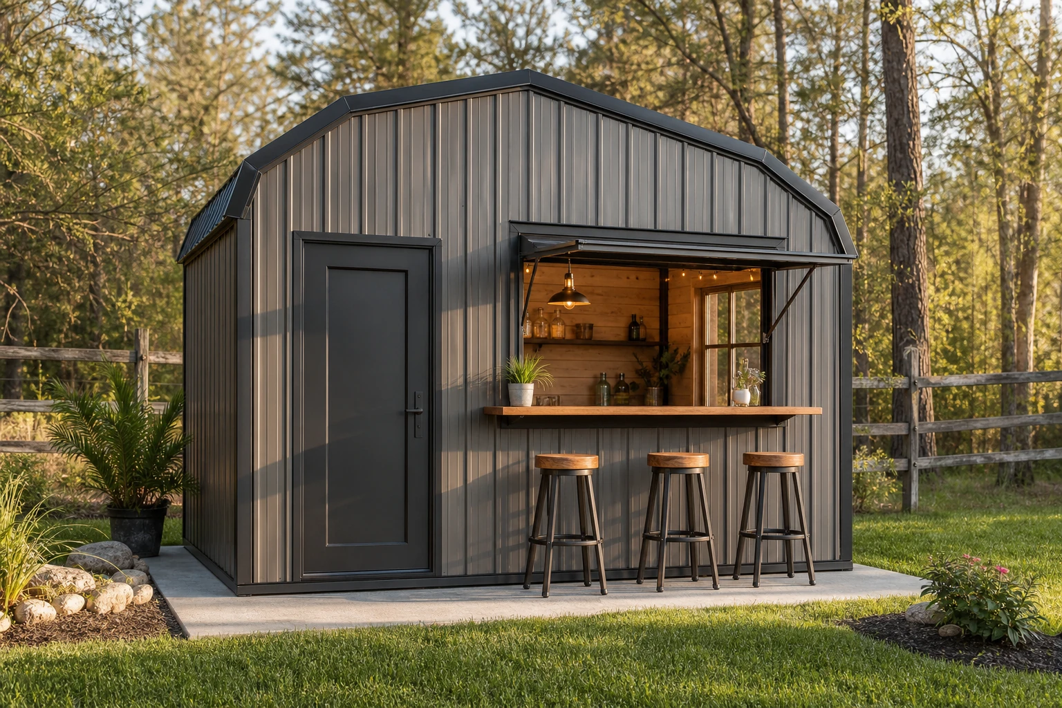
Compact gambrel profile
A compact double-slope roof with separate lower and upper pitches, useful loft volume, storage openings, and a matching profile-specific truss basis.
Open matching drawing set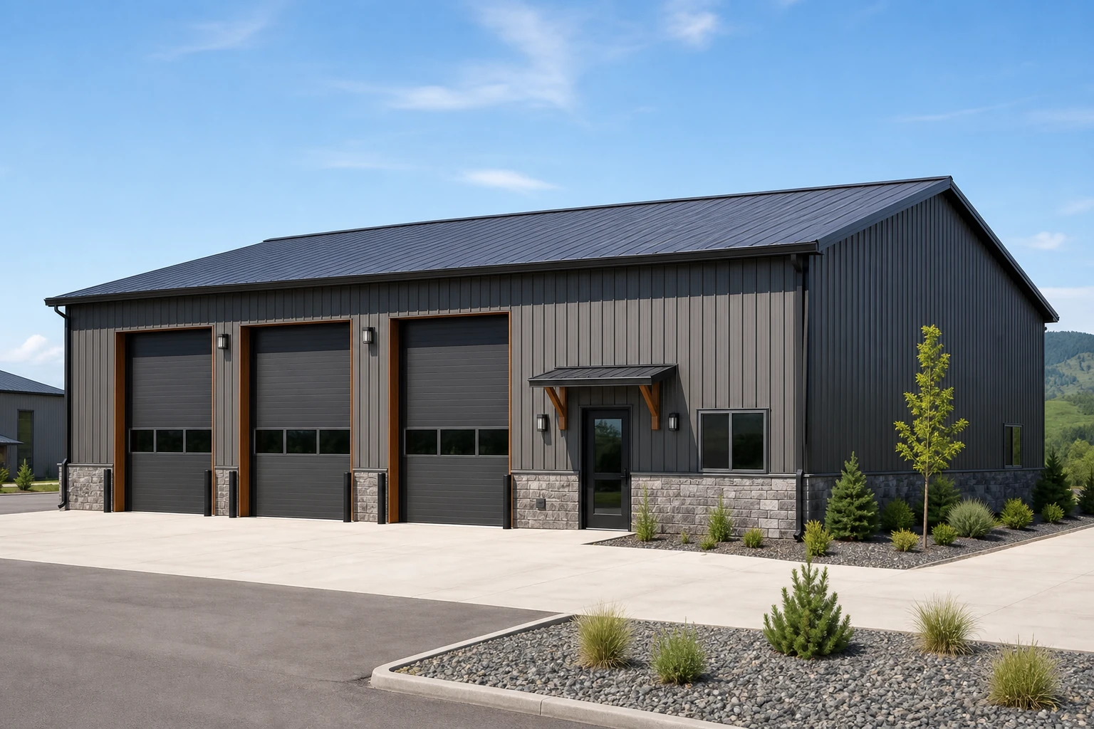
Custom shop
A 2,400-square-foot work and storage shell with coordinated overhead openings, service doors, wall heights, roof geometry, and a matching takeoff basis. Larger custom options are available by request.
Open matching drawing setSteel engineering handoff
Steely develops the coordinated cold-formed steel information for the agreed scope, then packages it so the engineer can review the actual geometry, site criteria, members, loads, openings, and connections without rebuilding the project intent from scratch.
When the structure is steel
Our coordinated steel scope can include member, panel, truss, joist, header, bracing, connection, production, and takeoff information for licensed project review.
When the structure is wood
Steely can provide the rendering and dimensioned architectural design information, but wood structural engineering must be completed by the customer's architect or appropriately licensed engineer unless separately contracted.
After approval
Labeled studs, track, headers, truss or joist components, connection information, and coordinated assembly documents.
Wall, floor, and roof panels organized for the approved building, openings, sequence, delivery plan, and site assembly.
Connect the approved package to qualified erection or a coordinated construction path where project location and scope align.